Hi, I'm and engineer and have a background of CNC machining and toolmaking and have recently been interested in making a RepRap type 3D printer for myself.
What I'm thinking of making is an aluminium frame based machine of high accuracy. I have access to CNC milling centres and turning centres and a large supply of surplus materials and parts from my work. I probably have access to bigger and better machines than the professionals actually make these machines on :)
The machine will be built mostly in my home workshop though using manual machinery.
After making a few initial sketches and models in Solidworks I seem to have question after question about the project, most of which regarding the electrical side of things and what temperatures / forces are required for the machine to work successfully.
The design so far..
The base of the machine is a 32mm 6061 plate 350mm x 450mm and the two uprights are 38mm square 6061. This is all surplus material from work, but think I might go for 50mm square for the uprights just to be a bit more rigid.
Linear rails are eBay type 12mm items which I think should be sufficent for the machine. Travels will be approx X 250, Y 200 and Z 150.
X axis is driven by a Nema 23 200step stepper driving a 25mm pulley giving a 0.025mm resolution with 1/16steps.
Y axis is similar to the X with Nema 23 200step stepper and 25mm pulleys giving a 0.025mm resolution with 1/16steps.
For the Z Axis I have a surplus NSK 16 x 2.0 pitch high precision ground ball screw which should be more than suitable. I should be able to get 0.01 resolution without microstepping, using a Nema 23 200 step motor. Not sure if this will be powerful enough to drive the ball screw directly?
The extruder design is something that I think is very critical to the quality of the parts produced and will take alot of development to get working perfectly. The design I have come up with uses a similar technique to MIG welders to feed the filament, using grooved rollers. The grooved rollers give nearly full point contact around the filament and I think won't deform it as knurled rollers might. I have the option in my design to change to knurled rollers easily if needed though. The rollers are grooved to accept both 3.0mm and 1.75mm filament.
The filament is guided to the rollers from a 316S/S guide then into a PTFE liner to a brass nozzle which for now I have designed with a 0.5mm tip, but this can easily be replaced with a smaller nozzle (which I think will be needed for better quality). I'm not sure what I'm going to use to heat the filament yet though. I plan to use a belt drive as opposed to a gearset for the extruder as this will eliminate backlash when retracting between extrusions.
The table is 200mm x 200mm, 12mm 6061 plate insulated to a peice of 20mm plate 200 x 200 with four 400W heating elements. I think this might be an overkill, but I should be able to make the elements switchable to use 4 elements to bring it up to temp then 2 to keep it there. Not sure yet. And also not sure what material to insulate the table with.
The heating elements are:
www.trademe.co.nz/Browse/Listing.aspx?id=410682530
Models of the design..
 |
| Extruder design. Missing detail of fastners, toothed belt, feed roller tensioner springs. |
 |
| Section view front of extruder. |
 |
| Section view extruder left end |
 |
| Machine front. X Axis drive belt is still a work in progress. |
 |
| Machine right end. |
 |
| Machine top view. |
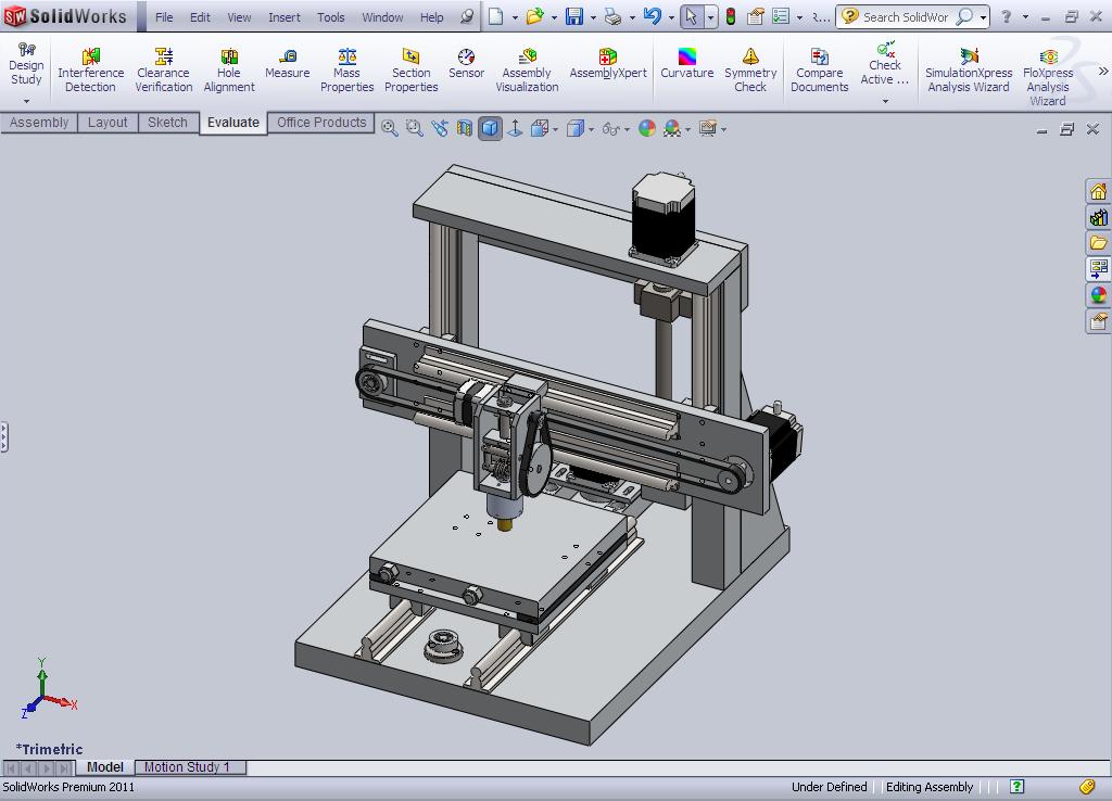
 |
| Machine trimetric view. |
Please look over my design so far and be critical. I'm extremley open to suggestions for improvements. I really want to hear what works well and what doesn't.
I intend to make the solidworks models available when the machine is completed but don't see too much point making them available before the machine is actually tested and working.
Let me know what you think :)
Cheers, Nigel.


